A standard single-mode fiber spec sheet lists core, NA, MFD, attenuation, and dispersion. A specialty fiber spec sheet adds parameters that standard single-mode sheets do not have: polarization crosstalk, absorption coefficient, d/Λ, effective mode area. Each parameter maps to a specific limitation of standard single-mode fiber. Choosing the wrong fiber — standard single-mode where polarization-maintaining is required, or a small-core gain fiber for a high-power system — surfaces the problem in the field, where rework costs far exceed the minutes spent checking specs at selection time.
This article answers one question: How do you read the specs of specialty fiber? Start with four common design aims: polarization-maintaining (PM), doped gain (Yb/Er/Tm), photonic crystal (PCF), and large core (LCF). These features can be combined, as in a large-core, PM, double-clad gain fiber. Check their specifications together when selecting a fiber.
This article explains each type’s structure, its spec parameters, and its usage constraints, and shows how to read the spec sheet using named products. The common parameters (core/NA/MFD/cutoff/attenuation) are covered in the single-mode and multimode articles of this series.
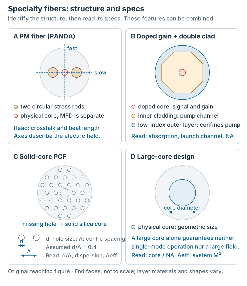
Figure 1 | Identify design features from the end face, then read their specs. The missing PCF hole leaves solid silica; the dashed circle only marks its position. The drawing assumes d/Λ = 0.4. Features can be combined; dimensions are not to scale and physical core size is distinct from MFD. Click to view full size.
1. Four limitations of standard single-mode fiber, and the four specialty types
Standard single-mode fiber has four limitations:
- Random birefringence: the stress inside the fiber is not symmetric, and the polarization state of light drifts as it propagates. After passing through a standard single-mode fiber, the output polarization direction is unpredictable[1].
- No gain: the glass does not amplify light.
- Dispersion and mode field fixed by the glass composition: the zero-dispersion wavelength of silica single-mode fiber is near 1310 nm (see the single-mode article of this series), and the mode field is set by the core diameter and the index difference, so the design freedom is limited.
- Small core limits power: the 9 μm core has a small mode field, and at high power the optical intensity is high, so nonlinear optical effects and material damage become problems[2].
The four design aims and corresponding parameters are listed below; the categories can overlap:
| Type | Structure | Solves | Type-specific spec parameter |
|---|---|---|---|
| Polarization-maintaining (PM) | core + two stress rods (PANDA) | random birefringence | polarization crosstalk, beat length |
| Doped gain (Yb/Er/Tm) | doped core; may use double cladding | no gain | absorption coefficient (dB/m, wavelength, launch channel) |
| Photonic crystal (PCF) | air-hole lattice cladding | fixed dispersion | d/Λ, effective mode area |
| Large core (LCF) | core 20–100 μm | small core limits power | core size, NA, M² |
For an approximately step-index specialty fiber, V, core size, NA and wavelength give an initial mode check. PCF and other index profiles require their own models and product specifications; the step-index cutoff does not apply directly.
2. Polarization-maintaining fiber: strong birefringence and the fast/slow axes
A PM fiber does not eliminate birefringence. It builds in a strong, well-defined internal birefringence (high-birefringence fiber, HIBI)[1]. A common implementation places two stress rods of a different glass composition (typically boron-doped, with a different thermal expansion coefficient) on either side of the core in the preform. After drawing, the stress rods create a well-oriented residual stress near the core, producing strong birefringence. This structure is a PANDA fiber; bow-tie shaped stress elements give a bow-tie fiber; an elliptical core produces form birefringence without mechanical stress[1].
Strong birefringence separates two orthogonal polarization modes into a fast axis and a slow axis. The slow-axis mode has a larger phase index and propagation constant, and a smaller phase velocity; the fast-axis mode is the reverse. These names concern phase and do not directly determine group velocity[3]. Launching along an axis and observing the product’s bend, stress and crosstalk limits suppresses coupling between the axes and gives more stable polarization[1][9].
The PM property is conditional: linear input polarization should align with one axis. Off-axis launch excites both components, whose relative phase changes with length; the output generally becomes elliptical. Arbitrary input polarization is not guaranteed to be preserved. In an ideal lossless model without axis coupling, a launch angle θ from the slow axis gives slow-axis power P cos²θ and fast-axis power P sin²θ. Beat length Lb = λ / |Δn| uses phase birefringence Δn; one beat length adds 2π of relative phase.
Spec parameters: in addition to the common parameters (MFD, cutoff, attenuation, NA), the PM spec sheet has polarization crosstalk (how much of the light launched on one axis appears on the orthogonal axis) and beat length. The selection criteria include beat length, operating wavelength, cutoff wavelength, attenuation, polarization crosstalk, MFD, fiber design type, coating, cladding diameter, and NA[1].
Usage constraints:
- Launching and splicing require rotational alignment. The splicer must identify stress elements; allowable angular error depends on the crosstalk/extinction target and supplier requirements. A 1–2° tolerance is not a universal PM fiber specification.
- Connectors must be keyed so that the stress rods align with the connector key[1].
Named product: Nufern (now Coherent) PM980B-XP, a bend-insensitive PANDA PM fiber. Its datasheet separately lists physical core diameter 5.5 μm and MFD 6.6 ± 0.5 μm @980 nm. They are distinct quantities. Core NA is 0.120, cutoff 920 ± 50 nm, attenuation ≤ 2.5 dB/km @980 nm, operating wavelength 970–1550 nm, and beat length ≤ 2.7 mm @980 nm. Normalized Cross Talk is ≤ −40 dB (4 m, 980 nm) and ≤ −30 dB (100 m, 980 nm); retain the corresponding test length when reading either value[9].
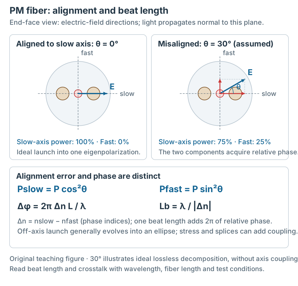
Figure 2 | End-face arrows show electric-field directions; propagation is normal to the end face. An assumed 30° input gives 75% slow-axis and 25% fast-axis power in the ideal uncoupled model. This is not measured product crosstalk. Beat length describes relative phase, not periodic power transfer between the axes.
3. Doped gain fiber: from core pumping to cladding pumping
A doped gain fiber dopes the core with a rare-earth ion (Yb, Er, Tm, etc.). The ion absorbs pump light and emits the signal by stimulated emission[5]. The gain window and pump wavelength are set by the ion:
| Ion | Operating wavelength (product spec) | Pump wavelength | Named product |
|---|---|---|---|
| Yb | 1060–1115 nm | 975 nm | LMA-YDF-25/250-M |
| Er | 1530–1565 nm | 980 / 1480 nm | EDFC-980-HP-80 |
| Tm | 1900–2100 nm | 793 nm | LMA-TDF-25P/250-LC |
The pump wavelength is the wavelength at which the spec sheet measures the absorption coefficient; 1480 nm for Er is a common pump in the literature[5].
Gain fibers come in two pump structures with different applications: single-clad (core-pumped) and double-clad (cladding-pumped).
Single-clad gain fiber is the basic type: the pump is coupled directly into the doped core, and the pump source must be single-mode to match the small core. Representative product EDFC-980-HP-80: small core (3.2 μm, MFD 5.8 ± 0.5 μm @1550 nm), spec lists core absorption 3.7 ± 1 dB/m near 980 nm[11]. This type is used in erbium-doped fiber amplifiers (EDFA): a 980 nm single-mode pump is combined with the signal via WDM, and both propagate in the core. EDFC-980-HP-80 has V ≈ 1.49 at 1550 nm (a = 1.6 μm, NA = 0.23), meeting the single-mode criterion in the step-index approximation[10][11].
Double-clad gain fiber is designed for high-power applications. Why double cladding: a high-power system needs high pump power, but high-power pump laser diodes are multimode (large NA, broad spectrum) and cannot be efficiently coupled into a small doped core. Double cladding solves this: the large inner cladding accepts the multimode pump, the pump is guided by the inner cladding and makes many transverse passes through the doped core where it is gradually absorbed, and the signal in the small core is amplified. A low-index outer layer confines the pump and can be made from low-index polymer coating. Representative products: LMA-YDF-25/250-M (nominal 25 μm core + nominal 250 μm inner cladding, spec lists cladding absorption 4.8 dB/m near 975 nm), LMA-TDF-25P/250-LC (cladding absorption 3.0 dB/m @793 nm) [10][12].
Spec parameters:
- Absorption coefficient (dB/m, pump wavelength, launch channel): the launch channel (core or cladding) is part of the spec — the core absorption of EDFC-980-HP-80 and the cladding absorption of LMA-YDF-25/250-M are not directly comparable[10][11][12]. Absorption is also distinct from amplifier gain; read it with fiber length, pump power and operating conditions.
- Core size and core NA: set the mode field and the single-mode/multimode condition.
- Cladding and cladding NA (double clad): core NA and cladding NA describe different interfaces. For example, First Cladding NA (5%) ≥ 0.46 applies to LMA-YDF-25/250-M, not to every gain fiber[10].
- Operating wavelength: the gain window.
Pumping at 980 or 1480 nm produces different inversion and noise behavior; actual noise figure also depends on pump power, fiber length, signal loading and amplifier design. Pump wavelength alone does not determine it[5].
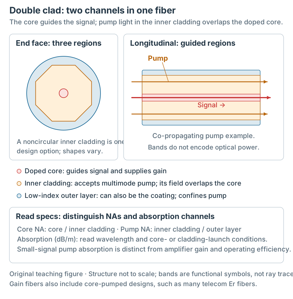
Figure 3 | Three regions and two optical channels of double-clad fiber. Longitudinal bands and arrows mark guided regions and a co-propagating pump example, not individual ray paths or pump attenuation and signal gain. Structure is not to scale; the low-index outer layer can also be the coating.
4. Photonic crystal fiber: air holes set the modes and dispersion
The cladding of a PCF is a periodic air-hole lattice (typically triangular), with one hole missing at the center to form a solid core. In the effective index model, the missing-hole region has the higher effective refractive index and acts as the core[7].
The key spec parameter is the ratio of air-hole diameter to lattice pitch, d/Λ:
- A sufficiently small d/Λ can reach the endlessly single-mode region in a particular solid-core triangular lattice with one missing hole. The numerical boundary cited by Mortensen et al. is approximately d/Λ = 0.406, for an ideal geometry and fixed silica refractive index[13]. This is not a universal 0.45 threshold for arbitrary PCF, nor a guarantee of low loss at every wavelength.
- λ/Λ, the number of hole rings, material, bending and manufacturing defects can affect the usable wavelength range; d/Λ alone does not specify loss or operating range.
Other spec parameters:
- Effective mode area: a PCF can be designed smaller or larger than standard single-mode. A small mode area enhances nonlinear effects[7].
- Dispersion: PCF offers large flexibility in dispersion engineering and can achieve anomalous dispersion in the visible range, which standard fiber cannot[7].
Usage constraints: the mode field of a small-core PCF does not match standard single-mode fiber, so direct coupling is inefficient. A tapered PCF improves the coupling[7].
5. Large core fiber: power density and M²
LCF cores commonly span 20–100 μm. One design aim is a larger effective mode area Aeff, reducing intensity and nonlinear effects at equal total power. A larger physical core does not necessarily enlarge the excited mode field in proportion. Power handling also depends on material, end faces, cooling and operating conditions; core diameter alone is insufficient[2].
Spec parameters:
- Core size and core NA: give an initial check of supported modes. LMA-GDF-25/250-M (core 25 μm, core NA 0.065) has V ≈ 4.8 at 1064 nm (V = 2π·a·NA/λ, a = 12.5 μm), exceeding 2.405 in the ideal weak-guidance step-index model and allowing higher-order modes. V²/2 is a large-V asymptotic estimate; it is not used here to claim an exact mode count. V does not directly determine M².
- Cladding NA: ≥ 0.46 (double-clad structure; the cladding can carry pump light, see section 3).
- Operating wavelength: 1060–1600 nm (LMA-GDF-25/250-M spec)[8].
- M² / beam quality: supported mode count does not directly determine output quality. Launch conditions, mode coupling and filtering all change the output field; check the system specification or actual M² measurements.
The “Matched” in LMA-GDF-25/250-M refers to the manufacturer’s matched series, including LMA-YDF-25/250-M; the series is designed for splice compatibility[10]. Equal 25 μm core diameters alone do not prove matched mode fields. Check index profiles, mode fields and splice conditions as well.
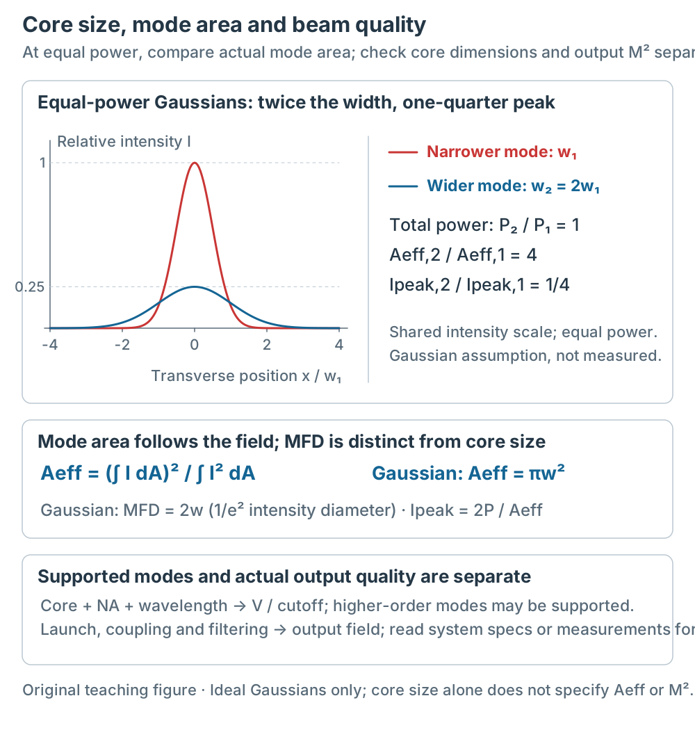
Figure 4 | Equal-power ideal circular Gaussians. With assumed w₂ = 2w₁, Aeff₂/Aeff₁ = 4 and peak-intensity ratio is 1/4. Both curves share one intensity scale rather than being individually peak-normalized. MFD = 2w is the 1/e² intensity diameter, distinct from physical core size. These are teaching assumptions, not measured mode areas or M² values for the listed products.
Back to the opening question: how do you read the specs of specialty fiber? The answer is four steps: first identify the type (which limitation of standard single-mode it solves), then read the common parameters (core/NA/MFD/cutoff/attenuation), then the type-specific parameters (polarization crosstalk, absorption coefficient, d/Λ, effective mode area, M²), and finally check the operating-wavelength conditions.
Conditions and limitations:
- Named-product values apply only to those models and conditions. Distinguish nominal values, tolerances, upper bounds (≤) and lower bounds (≥); they are not universal specialty-fiber specifications.
- PM crosstalk values now include manufacturer test conditions. The PCF hole ratio and Gaussian width ratio are drawing assumptions; no specific PCF product is specified.
- The V-parameter calculations use the step-index model and do not apply to PCF or other special index profiles.