A machine tool must know its axis position. Position feedback can provide a fine output step, while accuracy must be checked separately. A motor encoder measures motor angle, not carriage displacement directly. This article answers one question: How does an optical scale convert displacement into an electrical signal, and how does it reach nanometer resolution?
The answer: photoelectric scanning converts relative scale/head displacement into periodic signals. Incremental cycle counting and phase interpolation provide fine output steps; some models offer 1 nm versions, which does not imply 1 nm accuracy. The scale measures position between the scale and head; suitable mounting and control reduce the effect of screw-transmission errors on carriage positioning.
This article covers the grating and photoelectric scanning principle, how interpolation reaches the nanometer range, the difference between resolution and accuracy, and the limits from temperature and contamination.
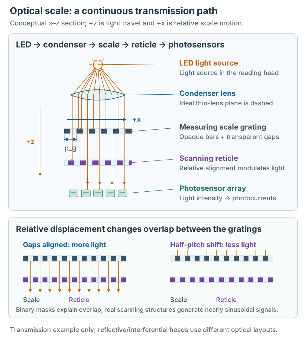
Figure 1 | Conceptual x–z transmission section. Orange rays propagate along +z and become parallel at the ideal thin condenser. Opaque bars stop light; relative scale/head motion is along +x. The binary masks below illustrate overlap, while nearly sinusoidal signals require the complete scanning structure[1]. Not to scale or a product cross-section; reflective and interferential heads use different paths. Click for full size.
1. The problem: a motor encoder does not measure the workpiece
A motor encoder is mounted on the motor shaft and measures the motor angle. Between the motor and the workpiece there is still a ball screw, guideways, and bearings. The ball screw has lead error and backlash, thermal growth changes the screw length, and the guideways have friction. These errors lie outside the motor encoder’s measurement range.
With the scale and head mounted on the base and moving part, it measures their relative displacement. A position loop can therefore reduce carriage-position errors caused by screw backlash or thermal growth. Mounting, Abbe offset and workpoint deformation still need evaluation; it does not eliminate every workpiece error.
2. The principle: grating + photoelectric scanning turns displacement into a sinusoidal signal
Periodic measuring structures can be made on glass, glass ceramic or steel. Here p_g denotes physical grating period and p_s electrical signal period expressed as displacement. A 20 µm DIADUR chromium-line glass scale is one example[1]. Catalog values such as 4 µm or 0.512 µm may describe signal periods; check the column and model rather than treating every value as line spacing[2].
Renishaw’s hardened stainless-steel RTLA50 tape scale has a 50 µm pitch and works with an EVOLUTE absolute readhead. The manufacturer lists a 500 µm rideheight tolerance and contamination-resistant design; this is a different arrangement from Figure 1’s transmission glass scale[6][7].
Figure 1 illustrates transmission imaging: the LED and condenser illuminate the scale, whose pattern is modulated by a reticle with equal or similar period. Relative motion changes transmission; photosensors convert light intensity into electrical signals. Actual scanning structures and processing generate nearly sinusoidal signals; the simplified masks only explain transmission overlap[1].
Some fine-period encoders use phase-grating diffraction, recombination and interference. In the handbook’s interferential arrangement, moving by one physical grating period produces two signal periods, so p_s = p_g / 2. That is a different optical path from Figure 1 and not a universal ratio for every head[2].
Incremental scanning commonly uses two signals 90 electrical degrees apart. Figure 2 explicitly defines offset-removed, normalized A = cos φ and B = sin φ, with φ = 2πξ / p_s for relative displacement ξ. Reduce atan2(B, A) modulo 2π to a within-period phase 0 ≤ φ < 2π, then combine it with whole-period counting and a datum to determine complete displacement. Direction follows phase progression; which channel leads depends on wiring and coordinate convention[2].
Scale materials include glass, Zerodur glass ceramic, and steel. Zerodur has a thermal expansion coefficient near zero and is used for temperature-sensitive high-precision applications[2].
3. Resolution, accuracy, and three easily confused numbers
Interpolation subdivides the electrical signal period p_s. With M position steps per period, Δx = p_s / M. Figure 2’s 20 µm / 20 000 = 1 nm is an arithmetic example, not every head’s specification. The LIC 4100 product page offers a 1 nm measuring-step version; it is an absolute series, not a representative “4 µm interferential incremental scale”[4].
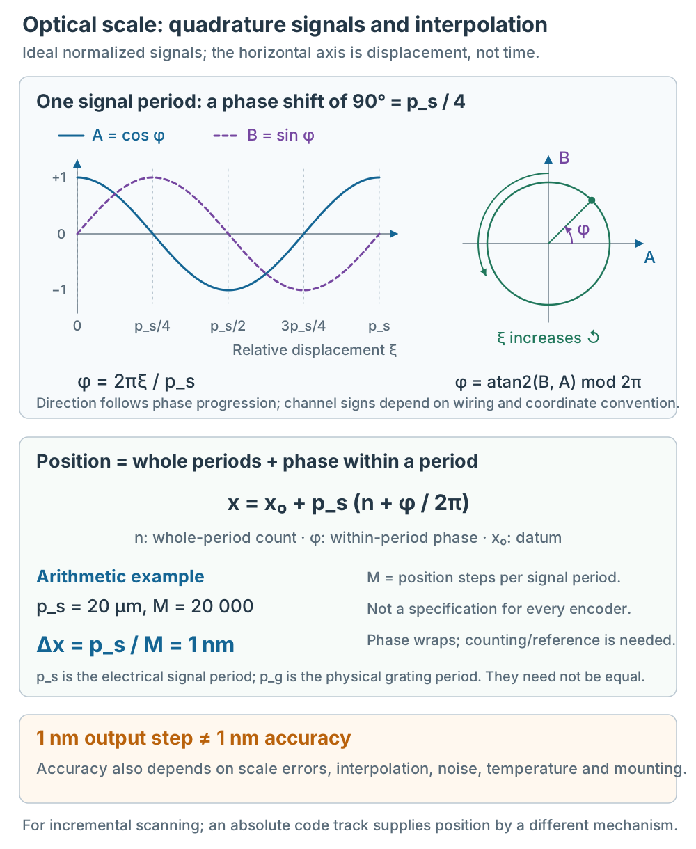
Figure 2 | Ideal quadrature waveforms and an A–B phase/direction circle. The horizontal axis is displacement, not time. Complete position combines whole-period count n, within-period phase φ and datum x₀. The 20 µm / 20 000 = 1 nm example describes output step, not accuracy. These ideal curves and arithmetic are not measured data. Click for full size.
Subdivision does not automatically remove scale or mounting errors. The following three quantities are not interchangeable accuracy specifications:
| Quantity | How to read it | Manufacturer example and conditions |
|---|---|---|
| Measuring step (resolution) | Smallest output position step, not accuracy | LIC 4100 offers a 1 nm version[4] |
| Baseline error F / accuracy grade | Longer-range scale error; check length, material and grade definition | LS 400 examples have ±3 / ±5 µm grades, not ±0.1 µm[1] |
| Interpolation error u | Systematic position error within one signal period | Distinguish maximum and typical values; do not combine different models[1][2] |
Baseline error F is measured at points spaced by integer multiples of the signal period to exclude within-period interpolation effects. Interpolation error u appears even at very low speeds and affects velocity control and surface finish; it is also distinct from repeatability and random noise[1].
Separate scale and readhead values in the Renishaw example: RTLA50 scale accuracy at 20 °C is ±10 µm/m. EVOLUTE offers 50, 100 or 500 nm resolution, ±150 nm SDE, noise below 10 nm RMS and a catalog maximum speed of 100 m/s. These describe accuracy, output step, within-period error, noise and speed, not a single positioning-accuracy figure[6][7].
An incremental encoder establishes its datum through reference marks; distance-coded versions identify a reference from neighboring mark spacings, with travel depending on model. An absolute encoder reads an absolute code track and can supply position at switch-on without first crossing an incremental reference mark. These are different referencing mechanisms[1][4].
Common misconception: a 1 nm resolution does not mean 1 nm accuracy. Resolution is the smallest distinguishable step; accuracy is the deviation between the measured value and the true value. A scale with 1 nm resolution may have an accuracy of ±1 µm / 1 m.
4. Limits: temperature, contamination, vibration, and mounting
Temperature: the scale and the mounting surface have different thermal expansion coefficients, so a temperature change alters the scale length and produces a local shift. The scale is calibrated at the 20 °C reference temperature, and the calibration curve is valid only at that temperature. When selecting a scale, match its thermal behavior to the workpiece or the measured object[1]. A Zerodur scale has a thermal expansion coefficient near zero, so the temperature effect is smallest.
RTLA50’s thermal expansion coefficient at 20 °C is 10.1 ±0.2 µm/m/°C. Independent expansion also depends on the FASTRACK carrier, datum fixing or adhesive mounting; material coefficient alone does not establish the installed thermal behavior[6].
Contamination: liquid droplets on the scale refract the parallel light like lenses, distorting the grating image and reducing accuracy. Heidenhain’s TRUE IMAGE TECHNOLOGY uses a special light-guiding element to remove the distortion, so the scale still measures accurately without purge air[1].
Vibration and mounting: optical scales are sensitive to vibration, straightness, and mounting error. A sealed scale has an aluminium extrusion housing and lip seals, suited to the dirty environment of machine tools; but the internal guided reading head introduces friction and hysteresis, which limit accuracy. An exposed scale is more accurate, but its scale face is open and needs protection[5].
5. The answer: the measurement role and applications of the optical scale
The scale and head convert relative displacement into periodic signals. Interpolation reads phase within a period; cycle counting and a datum turn phase into complete position. Some models offer 1 nm steps, while accuracy still depends on the scale, head, electronics, mounting and workpoint conditions. A position loop can feed back carriage position without guaranteeing elimination of every workpiece error.
Applicable conditions: applications needing micrometer-to-nanometer position feedback — CNC machine tools, coordinate measuring machines (CMM), semiconductor wafer stages, PCB assembly equipment[2][5].
Limits the sources do not resolve: the Heidenhain and Renishaw values come from their respective product information. Other vendors, such as MITUTOYO, require their own specifications. The accuracy of an optical scale depends on mounting, so the same scale achieves different real-world accuracy on different machines.
Self-check questions:
- Where is the measurement point of a motor encoder different from that of an optical scale? Why does this affect accuracy?
- The signal period is 20 µm; how is a 1 nm measuring step achieved? Must the physical grating period be the same?
- What do the three numbers — resolution, baseline error, and interpolation error — each describe?
- Why is the temperature effect of a Zerodur scale smaller than that of a glass scale?
- What environment is a sealed scale suited to, and what environment is an exposed scale suited to?