Telecom multimode fiber commonly uses 50/125 or 62.5/125 μm nominal core/cladding dimensions and guides multiple spatial modes. Differences in modal group delay spread pulses, affecting bandwidth and reach. It is widely used for short links in datacenters and buildings.
This article answers one question: how to read multimode OM grades and bandwidth? Start with modal dispersion, then OM classes, and finally read bandwidth with wavelength and launch conditions. Specific SR/DR reach and modulation are covered in the optical communication specification article [3].
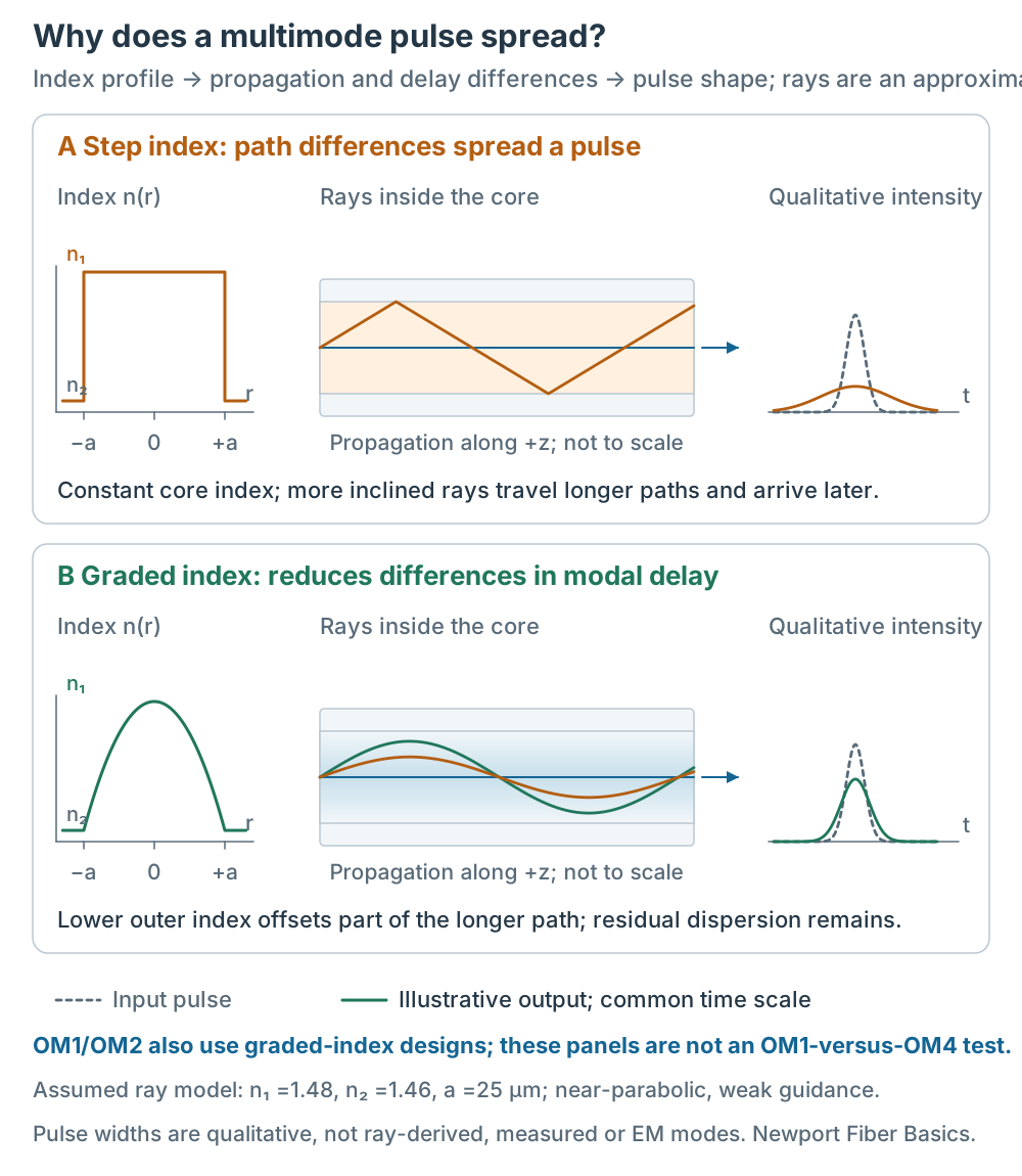
Figure 1 | Read index profile, propagation and pulse shape in sequence. Rays use explicitly assumed geometric-optics/weak-guidance approximations, not electromagnetic modal solutions. Pulse widths are qualitative and are not calculated from the rays; both panels use a common time scale. This explains index-profile design rather than measured OM1-versus-OM4 performance [5][7][11]. Click for full size.
1. Multimode and Modal Dispersion
Modal dispersion comes from different modal group delays: energy injected together reaches the output at different times. Ray paths provide an intuitive approximation; actual guided modes follow the electromagnetic field and fiber index profile[1][5].
- Step index: nearly constant core index. In a simplified meridional-ray model, more inclined rays travel longer paths and arrive later than axial rays.
- Graded index: higher index at the center, decreasing outward. A near-parabolic design offsets part of the longer path through lower outer index, reducing modal delay differences; residual dispersion remains[7][11].
OM1/OM2 also include graded-index designs. Their difference from OM3/OM4 is not simply step versus graded index. Modern laser-optimized fibers also control index profiles and differential mode delay (DMD). Mode count, core diameter or NA alone does not determine bandwidth; launch conditions affect which modes are excited.
Modal dispersion limits usable bandwidth. Longer links commonly increase spreading, while higher data rates reduce the tolerable time scale. Actual reach depends on transceivers, dispersion and loss budgets; 550 m is not a universal multimode maximum.
2. OM1–OM5: Same Dimensions, Different Bandwidths
OM identifies telecom multimode fiber classes[2]. The table lists common nominal dimensions and minimum bandwidth values in MHz·km; read them with the standard edition and product datasheet[6][9].
| Grade | Common core/cladding | OFL at 850 nm | EMB at 850 nm | OM5 values at 953 nm |
|---|---|---|---|---|
| OM1 | 62.5/125 μm | ≥200 | — | — |
| OM2 | 50/125 μm | ≥500 | — | — |
| OM3 | 50/125 μm | ≥1500 | ≥2000 | — |
| OM4 | 50/125 μm | ≥3500 | ≥4700 | — |
| OM5 | 50/125 μm | ≥3500 | ≥4700 | OFL ≥1850; EMB ≥2470 |
“—” means this table has no specified value, not that the fiber has no bandwidth. Dimensions show common cabling products; check older standards for their OM1/OM2 size classifications[7].
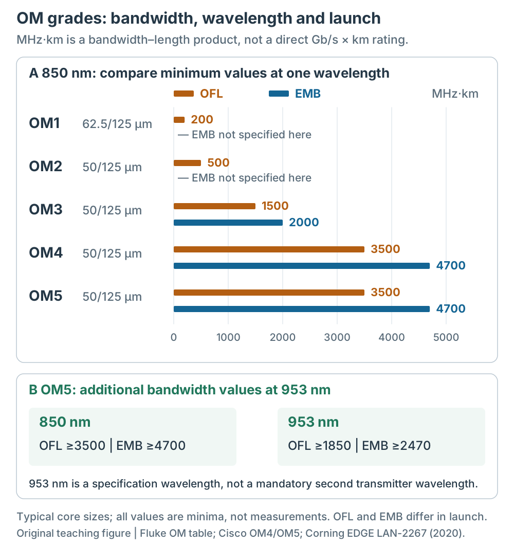
Figure 2 | Orange shows OFL and blue EMB, separating different launch/assessment conditions. OM4 and OM5 have the same minimum values at 850 nm; OM5 also specifies 953 nm performance. Values are minima, not measurements or direct ratings of data rate or reach [6][9].
OM3, OM4 and OM5 all commonly use 50 μm cores. Their bandwidth differences reflect design and specification control, not progressively smaller cores. An OM class is not a fixed line rate: do not assign OM1, OM2, OM3 and OM4 exclusively to 100M, 1G, 10G and 400G.
OM5 adds wideband specifications. 953 nm is a specification wavelength, not a requirement to transmit at both 850 and 953 nm. One common four-wavelength SWDM arrangement uses 850, 880, 910 and 940 nm. Channels and reach depend on the transceiver; OM3/OM4 can also support certain SWDM systems[10]. Evaluate OM5 against the equipment’s actual bands and support table.
3. OFL, EMB and Mode-Conditioning Cords
MHz·km is a bandwidth–length product, not a directly usable data-rate–distance rating. Modulation, source spectrum, receiver, coding and link budget also affect data rate.
OFL (overfilled launch) broadly excites modes for OFL bandwidth characterization. It is not a universal worst case for every laser launch. EMB (effective modal bandwidth) assesses laser-launch-related modal bandwidth using DMD and launch weighting. It does not mean bandwidth measured after installing a mode-conditioning cord[7].
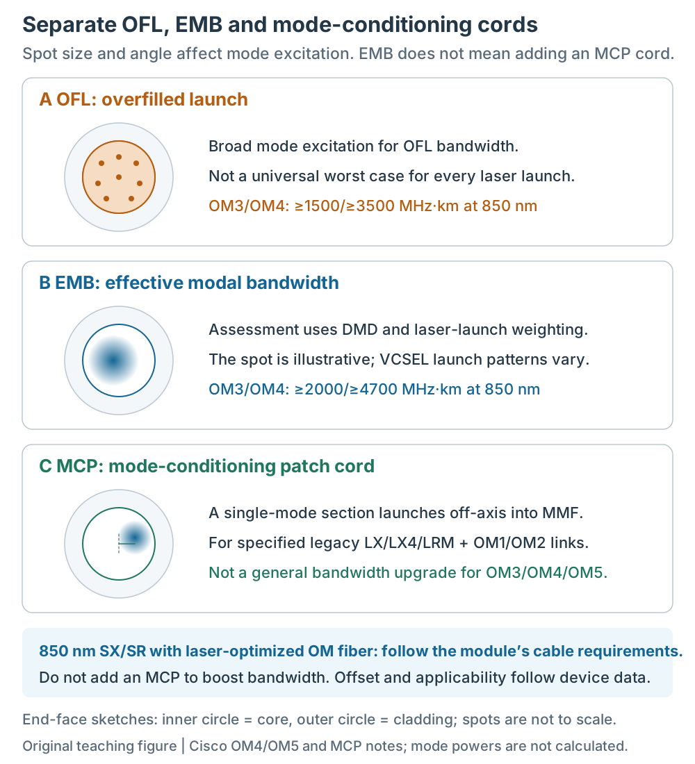
Figure 3 | The rows have different purposes. Inner circles show cores and outer circles cladding. Spots are not to scale and modal powers are not calculated. The EMB spot is not a fixed VCSEL field. The MCP row illustrates offset launch, not exclusive excitation of higher-order modes or a complete cable assembly [7][8].
A mode-conditioning patch cord (MCP) uses an off-axis single-mode-to-multimode launch to change mode excitation. It applies to specified legacy links, such as certain 1300 nm 1000BASE-LX/LH, 10GBASE-LX4 and 10GBASE-LRM applications over OM1/OM2. Check module and fiber requirements[8].
Do not add this MCP to 850 nm SX/SR and laser-optimized OM fiber to boost bandwidth. The OM3/OM4 values 1500/3500 are OFL minima and 2000/4700 EMB minima, not without/with-MCP figures. An MCP also does not upgrade OM1/OM2 to meet 100G fiber requirements.
4. How to Read a Spec Sheet
For “50/125 μm, OM4, OFL ≥3500 MHz·km at 850 nm”:
- 50/125 μm: nominal core and cladding diameters.
- OM4: fiber class, without specifying a complete link’s line rate or reach.
- OFL, 850 nm, ≥3500 MHz·km: launch condition, wavelength and minimum bandwidth.
Then check EMB, NA definition, attenuation, connectors, fiber count and the transceiver’s supported class, band and link length. Bandwidths at different wavelengths are not interchangeable. Keep source, launch and test conditions explicit. MPO/MTP or LC interfaces follow equipment and cabling architecture, not a simple single-mode/multimode distinction.
Low OH/High OH and Wavelength Ranges
OH-related absorption affects silica transmission spectra; the water peak near 1383 nm is a familiar example. Low OH/High OH labels commonly appear on laboratory step-index multimode fibers and patch cables and describe a different specification dimension from OM class.
Ranges such as 400–2400 nm for Low OH or 250–1200 nm for High OH are examples for particular product families, not fixed ranges for all multimode fibers. Check the model’s transmission/attenuation, operating wavelengths and reliability conditions[4]. Low OH alone does not establish OM4 compliance or high-speed telecom suitability.
5. Applications and Limits
Multimode is common in datacenters, building networks and SANs. Larger cores assist coupling, while modal delay, chromatic dispersion and loss jointly constrain reach. Compare complete transceiver and cabling costs rather than inferring them solely from MPO, LC or fiber type.
Bandwidth is a fiber product/class specification. Field acceptance also checks length, loss, connector cleanliness and polarity under cabling and application requirements; ordinary field loss tests do not directly measure EMB[6]. For communication reach and PAM4/PAM8, see the optical communication specification article .
Common Misconceptions
- “A larger core has higher bandwidth”: geometry alone is insufficient; index profile, DMD, wavelength and launch conditions also matter.
- “OM3 and OM4 are the same”: common dimensions match but minimum bandwidths differ. Check equipment reach support.
- “OM5 always reaches farther than OM4”: evaluate equipment bands and support data; minimum bandwidths at 850 nm match.
- “EMB is the benefit of adding MCP”: EMB is a bandwidth metric; MCP is a launch accessory for specified links.
Self-Check
- Why does modal dispersion spread a pulse?
- Why does core diameter alone not determine the OM class?
- How do OFL, EMB and MCP differ in purpose?
Read model and OM class → wavelength and OFL/EMB → transceiver and reach → loss and installation conditions. Explicit wavelength and launch conditions connect a bandwidth number to an actual link.