High-power lasers are the core tool of modern manufacturing: metal cutting, deep-penetration welding, and marking all demand a source that is simultaneously high-power, stable, and of good beam quality. The traditional answer was the solid-state rod laser, but it hits a fundamental wall: thermal lensing. A laser rod absorbing pump power develops a radial temperature gradient; the refractive index changes with temperature, and the rod itself becomes an unstable lens. The higher the power, the stronger the thermal lens, and the worse the beam quality and stability — which is why rod lasers have struggled to scale to kilowatt levels while keeping a fine focus.
Beam quality is not a luxury: it directly sets the focus spot size and the kerf width in cutting. A beam that cannot be focused finely is just a bigger torch, not precision manufacturing. The real question is therefore: how do you keep near-diffraction-limited beam quality at kilowatt-level output?
The answer is the fiber laser + MOPA (Master Oscillator Power Amplifier) architecture: the gain medium is a thin, long doped fiber whose geometry lets heat escape axially, making thermal lensing negligible; the system is split into a seed and amplifiers, where the seed sets beam quality and the amplifiers only boost power — the two are decoupled. This article explains the principle, the key components, and a concrete JPT MOPA optical path.
1. Thermal lensing, and the fiber’s geometry
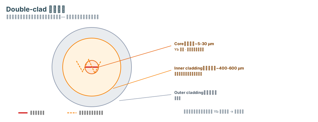
The rod laser’s problem is that its gain medium is a short, thick cylinder: pump is absorbed at the center, heat must conduct radially outward, and the temperature gradient is large. The fiber laser changes the geometry to long and thin: the gain medium is a doped fiber with a core on the order of 10 µm (20–30 µm for large-mode-area fiber; RP Photonics); pump light enters from the side (the inner cladding) and is absorbed as it propagates; heat conducts from the core through the coating into a metal tube and water cooling. The radial heat path is half the core diameter (on the order of 10 µm), far shorter than the millimeter scale of a rod, so the temperature gradient is far smaller, and thermal lensing is negligible (RP Photonics, Fiber Lasers).
This is the structural reason a fiber laser can hold a low M² (beam-quality factor; M² = 1 is the diffraction limit) at kilowatt power: the single-mode core supports only the fundamental mode, confining the beam to it, and at high power large mode area (LMA) fiber lowers the optical intensity and suppresses nonlinear effects such as stimulated Brillouin/Raman scattering (RP Photonics).
2. MOPA: the seed sets beam quality, the amplifier sets power
MOPA splits the laser into two parts:
- Master Oscillator (MO, the seed): generates the initial laser and provides the beam’s frequency, phase, and beam quality. The seed is a low-power single-frequency laser (milliwatt to watt level), of near-diffraction-limited beam quality (M² as low as 1.05–1.15; RP Photonics).
- Power Amplifier (PA): boosts the seed’s power to the target (tens of watts to kilowatts) without changing its beam quality, frequency, or phase.
The key is decoupling: the output M² is set by the seed. Amplify an M² ≈ 1.1 seed to kilowatts, and the output is still a near-diffraction-limited beam (the gain medium amplifies the field amplitude without changing the spatial mode). This is fundamentally different from a monolithic laser, which tries to produce high power and a good beam in a single cavity.
Why multi-stage amplification? Amplifying milliwatts to kilowatts in one stage would saturate the gain in the front of the fiber, leaving a non-uniform gain distribution that excites higher-order modes. In practice the chain is split into 2–4 stages, each providing 10–100× gain, with the pump power increasing stage by stage. Seed 10 mW → pre-amplifier (~100× gain) → 1 W → power amplifier (~100×) → 100 W → final stage (~10×, largest pump power of the chain) → 1 kW.
Why Yb-doped fiber? Yb’s absorption band covers 900–1000 nm, matching high-power pump diodes (915/976 nm); emission is 1060–1080 nm, with 1064/1080 nm the most common commercial wavelengths (RP Photonics). Yb³⁺ has a simple two-level energy structure; with 976 nm pumping (1064 nm output) the quantum defect is only about 8% (1 − 976/1064), so it generates less heat.
Pump combining: the gain fiber is double-clad — the signal travels in the core (single-mode), the pump in the inner cladding (multimode, 400–600 µm diameter; RP Photonics). A pump combiner (MPC) uses WDM to combine pump and signal in the same fiber; the pump is gradually absorbed by the Yb ions in the core as it propagates, transferring its energy to the signal.
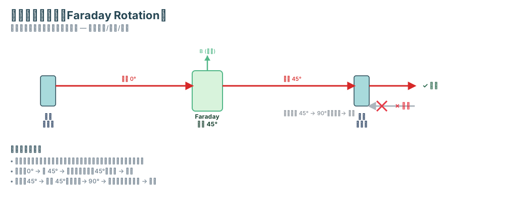
Isolators: connectors and splices in a high-gain amplifier produce back-reflections; fed back into the seed, they cause power fluctuations or damage. A MOPA places an optical isolator between each stage and at the output; the isolator uses Faraday rotation (a non-reciprocal effect) to let light pass in one direction only.
Efficiency: modern Yb fiber lasers reach slope efficiency (pump light → signal light) above 50%, and the overall electro-optical (wall-plug) efficiency record from pump-diode electrical power to laser output approaches 65% (RP Photonics, Slope Efficiency). At 65% efficiency, 1 kW of output requires about 1538 W of electrical input, leaving about 538 W of waste heat — heat removal remains the main engineering challenge.
3. A concrete optical path: the JPT MOPA
JPT published a 3D animation of a MOPA fiber laser’s internal structure (source: the JPT video listed in the frontmatter), showing the main optical path of a commercial MOPA laser:
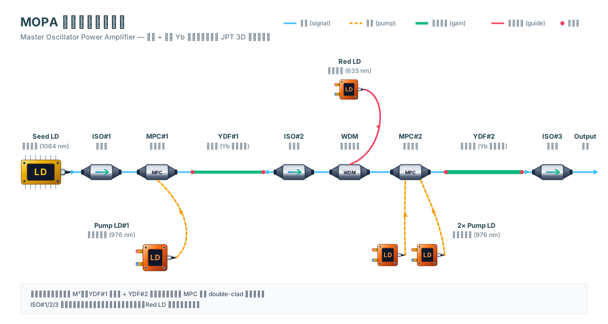
Path: Seed LD → ISO#1 → YDF#1 pre-amp (pumped by Pump LD#1 via MPC#1) → ISO#2 → WDM + Red LD → YDF#2 power amp (pumped by 2×Pump via MPC#2) → ISO#3 → Output.
Mapping back to the concepts above:
- Seed LD: the seed (master oscillator) — sets beam quality
- YDF#1 + 1 pump: pre-amplifier — first stage
- ISO#2: inter-stage isolation — protects the front stage
- WDM + Red LD: combines a visible red guide beam into the main path so the operator can see the processing point
- YDF#2 + 2 pumps: power amplifier — second stage
- ISO#3: output isolation — protects the whole amplifier chain
This machine uses two stages of Yb-doped fiber amplification, with 1 pump on the pre-amp and 2 on the power amp — staged pump management in practice. It is used for marking (tablets, phones, solar panels, metals, and more).
4. Where the power ceiling comes from: heat, ASE, and fiber damage
MOPA is mature, but the power ceiling is not infinite. The main limits:
- Waste heat: even at 65% efficiency, 1 kW of output still produces about 538 W of waste heat (1000/0.65 − 1000). The waste heat comes from two places: the gain fiber (quantum defect) and the pump diodes (electrical loss); the heat path is core → coating → metal tube → water-cooling plate. Poor thermal design directly degrades beam quality and power.
- Amplified spontaneous emission (ASE): in a high-gain amplifier, Yb produces a broad-spectrum background that consumes pump energy and adds noise. Multi-stage design and isolators suppress it.
- Fiber damage: at high power, micro-defects at splices, connectors, and end faces become damage points; splice quality and end-face cleanliness directly affect the damage threshold.
- Beam-quality degradation: excessive pump power excites higher-order modes and raises M²; LMA fiber and mode filtering (e.g., fiber coiling) keep the beam in the fundamental mode.
Back to the opening question: how do you keep near-diffraction-limited beam quality at kilowatt-level output? The answer: use the fiber geometry to eliminate thermal lensing, and use the MOPA architecture to decouple beam quality from power — the seed (M² ≈ 1.05–1.15) sets the beam, and the multi-stage Yb-doped fiber amplifiers only boost the power. The applicable regime is the 1064/1080 nm band at kilowatt to tens-of-kilowatt manufacturing powers; what the sources do not yet resolve is the single-fiber power ceiling (heat and nonlinear effects) and long-term reliability (pump diode and fiber lifetime) — multi-fiber beam combining is the current route past the single-fiber limit.