A fiber spec sheet reads “9/125, NA 0.14, MFD 10.4 μm, 0.2 dB/km” — each number specifies a different thing. Picking the wrong fiber — using multimode as single-mode, or standard SMF as low-loss SMF — only shows up in the field, and re-cabling costs far more than a few extra minutes checking specs at selection time.
This article answers one question: what are the fiber specs, and how to read them? The answer has three layers: fiber structure (core/cladding/NA), key parameters (MFD/attenuation/dispersion/bandwidth/cutoff/bend), and classification (single-mode/multimode/specialty/large-core).
This article gives the parameter map and classification, and shows how to read a spec sheet. The details of single-mode, multimode, and specialty fiber each have a dedicated article (this series).
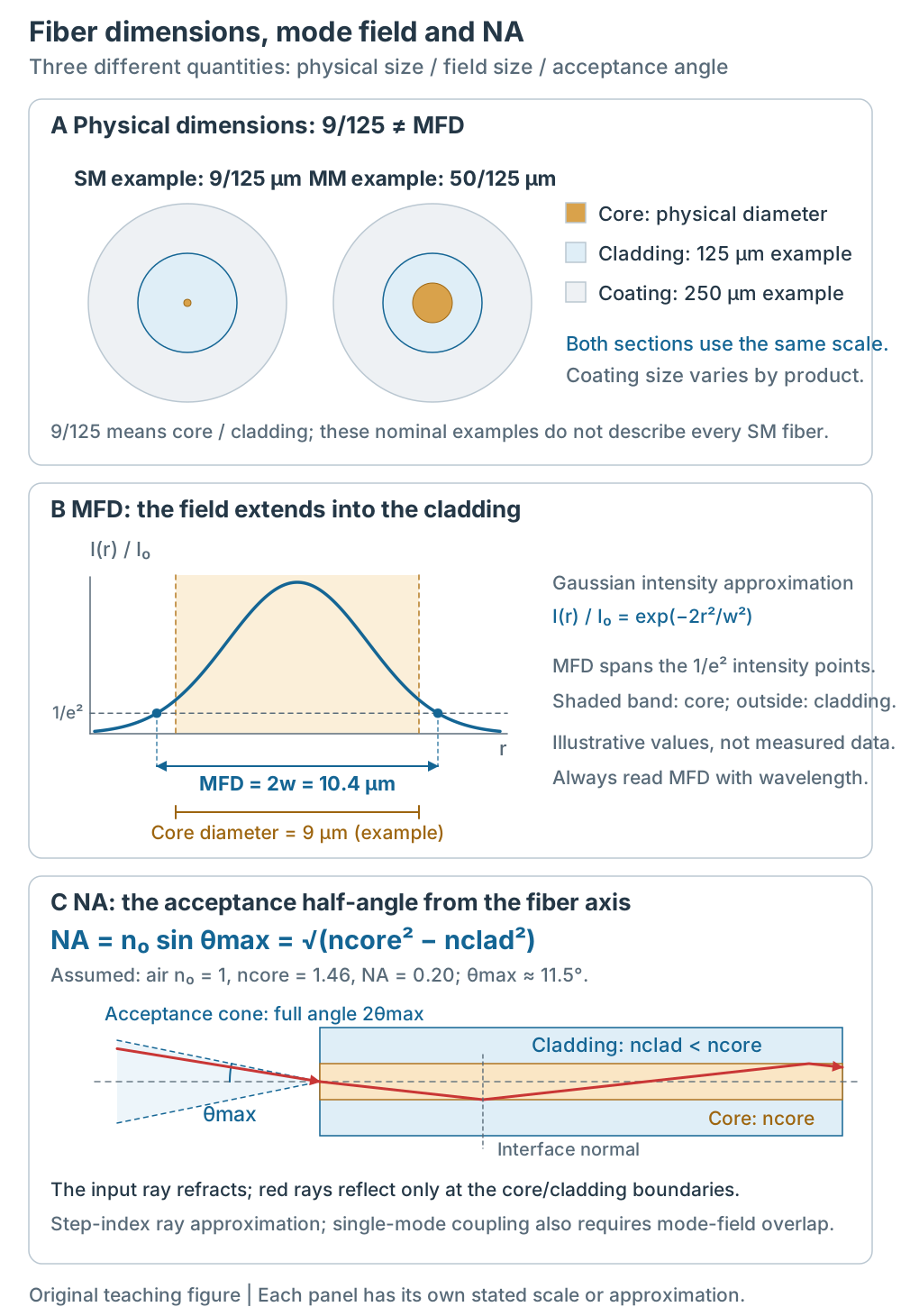
Figure 1 | Physical diameter, MFD and NA describe different quantities. The nominal cross sections share a scale; MFD uses a Gaussian intensity approximation; the step-index ray model refracts at the input and reflects at core/cladding interfaces. Each panel has its own scale or assumptions; these are not measured product profiles. Click for full size.
1. Fiber Structure: Core, Cladding, NA
A fiber has three layers: the core and lower-index cladding form the guiding structure, while the coating provides protection. Telecom fibers commonly have 125 μm cladding. “9/125” denotes a nominal core of approximately 9 μm and 125 μm cladding; common multimode examples are 50/125 and 62.5/125. Actual core and coating sizes depend on the model; not every coating is 250 μm[3][5].
For a step-index ray model, total internal reflection gives NA (numerical aperture) = n₀ sin θmax = √(ncore² − nclad²). Here n₀ is the incident medium’s index; θmax is the acceptance half-angle from the fiber axis, so the full cone angle is 2θmax. Only for air, n₀ ≈ 1, can this be written as NA = sin θmax[6]. Under the same model and external medium, higher NA means a wider acceptance angle. Single-mode coupling also depends on MFD, field shape and alignment. A single-mode datasheet may define NA by a far-field power threshold, so check the measurement method[5].
Coatings commonly use acrylate to protect the fiber. For example, SMF-28 Ultra offers 242 μm and 200 μm coating options[5]. Permitted bend radius also depends on fiber design, cable construction, wavelength and loading; coating diameter alone does not determine it.
2. Key Parameters
The key parameters on a spec sheet:
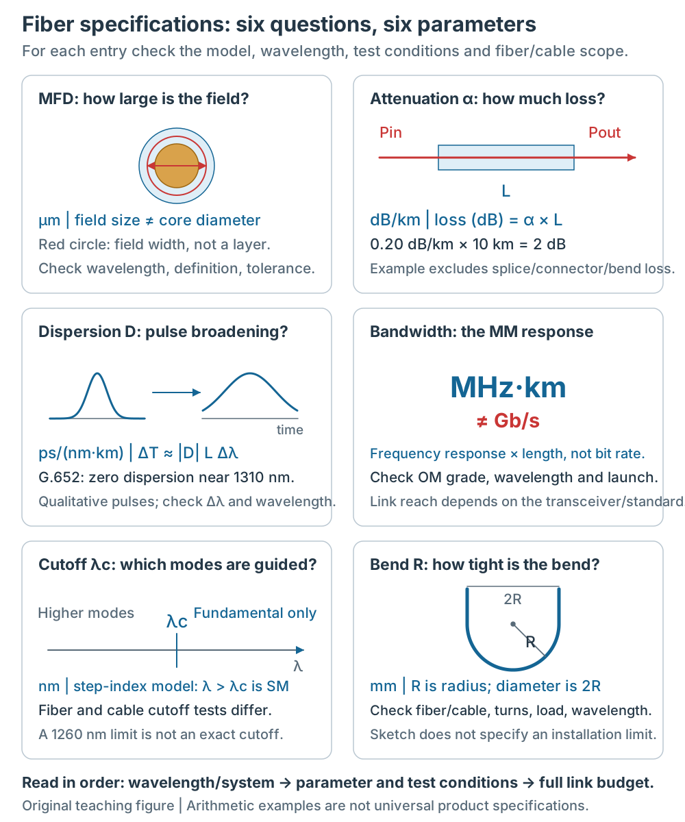
Figure 2 | Each parameter answers a different question. Pulse shapes and field extent are qualitative; the loss calculation covers fiber alone, and the bend sketch specifies no installation limit. MHz·km is not Gb/s, and an upper cutoff limit is not every fiber’s exact cutoff.
| Parameter | Meaning | Reading/example (not a universal limit) |
|---|---|---|
| MFD (mode field diameter) | mode field size | 9.2 μm @1310, 10.4 μm @1550 |
| Attenuation | loss per km | 0.35 dB/km @1310, 0.21 dB/km @1550 |
| Dispersion | group-delay difference per wavelength interval and length | G.652 zero-dispersion wavelength is near 1310 nm; SMF-28 Ultra: ≤18 ps/(nm·km) @1550 [5] |
| Bandwidth | multimode MHz·km | — (SMF uses dispersion) |
| Cutoff wavelength | higher-order-mode cutoff condition | Example: cable cutoff λcc ≤1260 nm, an upper limit rather than an exact value [5] |
| Bend radius | minimum bend | per model |
- MFD: the effective mode-field diameter, read together with wavelength. In the Gaussian intensity approximation I(r) = I₀ exp(−2r²/w²), MFD = 2w, spanning the two 1/e² intensity points. The field can extend into the cladding, so MFD differs from physical core diameter. The 9 μm and 10.4 μm values in Figure 1 illustrate this distinction, rather than measured dimensions of one product. Use the datasheet’s definition and tolerance for actual fibers[1][5].
- Attenuation: loss per kilometer, in dB/km. Fiber loss is approximately αL: 0.20 dB/km × 10 km = 2 dB. A complete link adds connector, splice and bend losses. Telecom SMF often has lower loss at 1550 nm, but check the model. OH absorption depends on manufacture; low-water-peak products should not automatically be excluded at 1383 nm[5][6].
- Dispersion: wavelengths have different group delays. For a narrow spectrum and approximately constant D, ΔT ≈ |D|LΔλ estimates the delay spread. G.652 has a zero-dispersion wavelength near 1310 nm; approximately 17 ps/(nm·km) must not be assigned to 1310 nm. SMF-28 Ultra, for example, specifies a 1304–1324 nm zero-dispersion range and ≤18 ps/(nm·km) at 1550 nm[5]. Spectrum, pulse chirp and compensation also affect actual transmission.
- Bandwidth: multimode fiber commonly specifies a bandwidth-length product in MHz·km. Check wavelength, launch conditions and OM grade; it does not directly convert to Gb/s or a universal reach. Single-mode fiber lacks intermodal dispersion between higher spatial modes, but still has chromatic dispersion and other system limits[2][6].
- Cutoff wavelength: in a step-index model, only the fundamental mode is guided above the relevant cutoff; higher modes may be guided below it. Fiber and cable cutoff have different test conditions. “λcc ≤1260 nm” is an upper specification limit, not an exact cutoff for every fiber[5][6].
- Bend radius: R is the radius; the bend diameter is 2R. Check fiber/cable scope, installation or service state, load, number of turns and wavelength. A mandrel bend-loss test does not directly specify a finished cable’s minimum installation radius[5].
3. Classification: Single-Mode, Multimode, Specialty, Large-Core
Common fibers can be grouped by guidance and use. Specialty and large-core describe applications and can overlap with single-mode or multimode:
| Class | Core | Use | Dedicated article |
|---|---|---|---|
| Single-mode (SMF) | 9 μm | long-haul comms, high power | Single-mode fiber |
| Multimode (MMF) | 50/62.5 μm | short-reach datacenter | Multimode fiber |
| Specialty | per type | PM, gain, special band | Specialty fiber |
| Large-core (LCF) | 20–100 μm | high-power laser delivery | Specialty fiber |
- Single-mode: small core (9 μm), one mode, no modal dispersion, long reach.
- Multimode: large core (50/62.5 μm), many modes, modal dispersion, short reach.
- Specialty: polarization-maintaining (PM), doped gain (Yb/Er/Tm), photonic crystal (PCF), etc., specialized by use.
- Large-core: 20–100 μm core, for high-power laser delivery (see the specialty fiber article).
Single-mode behavior depends on core size, NA and operating wavelength together. For a weakly guiding step-index model, V = 2πa·NA/λ, with core radius a; V < 2.405 gives the single-mode condition[6]. Diameter alone is insufficient, and this threshold does not apply unchanged to every specialty design. First check the system and transceiver’s supported fiber type, then the specific model.
4. How to Read a Spec Sheet
Example: “9/125, G.652.D, OS2, MFD 10.4 μm, 0.2 dB/km @1550”:
- 9/125: 9 μm core / 125 μm cladding (single-mode)
- G.652.D: ITU standard (standard single-mode)
- OS2: low-loss grade (0.4 dB/km max)[4]
- MFD 10.4 μm: the field diameter at 1550 nm
- 0.2 dB/km @1550: the loss at 1550 nm
Each number specifies a different thing; check them one by one when selecting.
5. Selection Decision
When selecting a fiber, ask four questions first:
- Distance: select by transceiver, transmission standard, wavelength and loss/dispersion budgets. Long reach usually uses SMF, but short links can also use it; 2 km and 550 m are not universal boundaries.
- Power: for high-power lasers, check power density, damage conditions, mode quality and end-face treatment; large-core fiber is one candidate.
- Polarization: need PM → PM fiber
- Gain: building a fiber laser → doped gain fiber
Distance and system compatibility jointly determine selection. Power, mode quality and polarization requirements influence whether specialty fiber is needed.
Besides these four questions, also confirm the wavelength (1310/1550 nm), connector (LC/SC/MPO), and compatibility with the existing datacenter. Write these into the spec sheet and check them one by one.
Common Misconceptions
- “A bigger core is always better”: Core size is one factor; also check modes, wavelength and system compatibility.
- “A bigger NA is always better”: A wider acceptance angle does not improve every coupling or transmission property. Single-mode coupling needs mode-field overlap; multimode performance also depends on index profile and launch conditions.
- “All single-mode fibers are the same”: They are not. G.652 (standard), G.655 (non-zero dispersion), G.654 (large area) each have uses; OS1/OS2 loss differs too.
Self-Check for the Reader
- Can you state the three fiber layers and what NA means?
- Is MFD the same as the core diameter?
- What is the divide between single-mode and multimode?
Back to the opening question: what are the fiber specs, and how to read them? The answer is structure (core/cladding/NA) + key parameters (MFD/attenuation/dispersion/bandwidth/cutoff/bend) + classification (single-mode/multimode/specialty/large-core). Read each number with its model, wavelength and conditions. Nominal dimensions, teaching examples and product-specific specifications have different scopes and must not be combined into a universal datasheet. The series’ single-mode, multimode and specialty articles cover the parameters in more detail.