Optical communications and optical interconnects must convert electrical signals into optical signals. The most direct method is to modulate the drive current of a laser diode directly (direct modulation), but that method changes the optical power and the optical frequency at the same time, producing chirp that limits the data rate and the reach[1].
External modulation separates the light source from the modulator: a continuous-wave laser supplies the carrier, and the modulator adds the signal. It permits independent control of the source and modulation. Low chirp still depends on the architecture, material and drive balance; an external modulator does not automatically eliminate chirp[1][9]. Research targeting 400 Gb/s per wavelength makes bandwidth, voltage and footprint important design constraints[2].
This article separates three questions: what the electrical signal changes (phase or absorption), how the optical structure reads it (MZ interference or ring resonance), and which material implements it (LN/TFLN, silicon or graphene). MZ and micro-ring are architectures; TFLN and graphene are materials, so these categories should not be treated as three competing architectures.
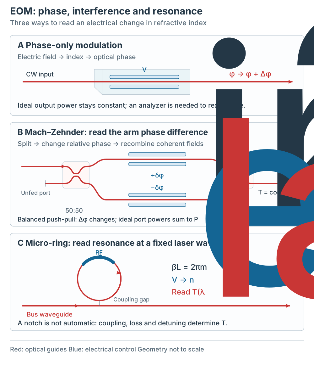
Figure 1 | Red paths are guided light; blue marks electrical control. Phase alone does not change ideal power. MZ splits and recombines fields; a ring couples across a gap. Conceptual topology, not to scale or a fabrication drawing. Click for full size.
Why use external modulation?
Direct modulation varies a laser diode’s drive current with the data, changing optical power and frequency together (chirp)[1]. Fiber dispersion converts these frequency changes into waveform distortion. Extinction ratio (ER) must be read with the measurement conditions: static transfer-curve ER and dynamic data ER are different quantities. Reported examples of 6–10 dB for direct modulation and above 20 dB for external modulation do not establish universal limits or an equal-condition comparison[1].
An EOM uses an electrical signal to control optical phase, power or polarization. The physical mechanism depends on the platform: LN/TFLN uses the Pockels effect, silicon commonly uses changes in free-carrier density, and an electro-absorption modulator changes absorption[3][7][9]. A phase change alone does not change ideal optical power; a readout structure is needed for intensity modulation.
Phase control and MZ readout
The Pockels effect is linear: Δn ∝ E. The Kerr effect is quadratic: Δn ∝ E2; devices based on the Kerr effect (Kerr cells) are uncommon[3]. The electro-optic coefficient r33 of lithium niobate (LiNbO3) is 30.8 pm/V (the source table does not state a wavelength)[4].
The voltage that produces a phase shift of π is called the half-wave voltage Vπ. A bulk Pockels cell has a Vπ of hundreds to thousands of volts and needs a high-voltage amplifier; a waveguide EOM has small electrode spacing, works at a few volts, and reaches higher modulation frequencies[3].
To read phase as intensity, one option is a Pockels cell between polarization optics: the input excites both crystal eigenpolarizations (for example at 45°), the cell changes their relative phase, and an output analyzer converts that retardation into power variation[13]. Simply adding a polarizer after a common phase shift is insufficient. A second option splits coherent light into two MZ arms and recombines them after changing their relative phase[3][9].
An MZ modulator has an input splitter, two phase-controlled arms and an output combiner. For ideal balanced arms and lossless 50:50 couplers, the selected port has T = Pout/Pin = cos2(Δφ/2); the complementary port has 1 − T. Write Δφ = φbias + πv/Vπ, with Vπ defined as the voltage increment at the specified drive port that adds π to the net two-arm phase difference. The definition already accounts for single-arm or push-pull drive; an extra factor of two must not be silently added[5][9]. Quadrature, Δφ = π/2, gives T = 0.5 and local small-signal linearity. It is not linear over an entire half-wave swing. Practical extinction is limited by loss and imbalance; coherent IQ transmitters combine MZMs to control both field quadratures[9].
The cited Ti:LiNbO3 example uses Vπ = 5.3 V at 10 Gbps, with DC bias near quadrature[6]. Treat these as conditions for that example. A drive below Vπ alone does not guarantee linearity or minimum chirp: signal excursion, arm imbalance and drive symmetry must also be considered[9].
Unstrained bulk silicon is centrosymmetric and lacks an intrinsic bulk second-order Pockels response in the usual model. Conventional silicon modulators use the plasma-dispersion effect: carrier depletion, injection or accumulation changes index and can also change absorption. This phase-control mechanism can be placed in either MZ or ring structures; it does not mean that every silicon-containing hybrid platform lacks a Pockels material[7].
High-bandwidth waveguide modulators often use traveling-wave electrodes. The microwave travels along the optical propagation direction; efficient broadband interaction requires matching its phase velocity to the optical group velocity, together with suitable impedance termination and low RF loss[14]. Electrode length or a material response time alone does not determine the finished device bandwidth.
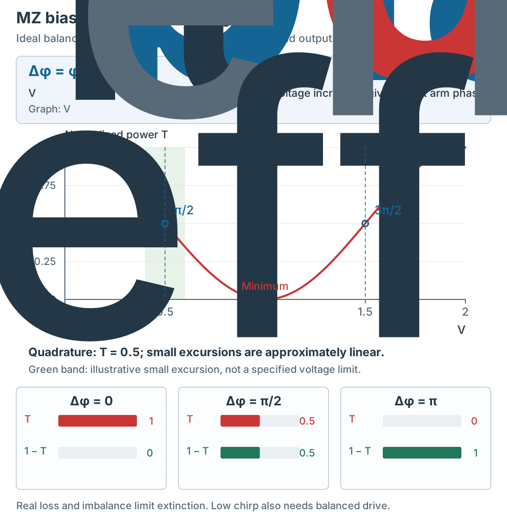
Figure 2 | The ideal balanced model defines Vπ for the net arm phase. Quadrature is locally linear for small signals. The green band illustrates an excursion, not a product limit. Real devices need loss, imbalance and chirp checks. Click for full size.
Micro-ring: read a moving resonance
A resonator supports only certain frequencies: when the round-trip phase shift is an integer multiple of 2π, the field adds to itself coherently and a resonance forms. The spacing between adjacent resonances is the free spectral range (FSR), the inverse of the round-trip time; the smaller the resonator, the larger the FSR[8].
A micro-ring couples to a bus waveguide across a gap. At resonance, the through-port field combines the direct bus field with the field coupled back from the ring. The resulting notch depends on interference, coupling and internal loss, rather than the ring simply absorbing all resonant light. In an ideal lossless single-bus ring, the power transmission remains unity while phase changes. A lossy ring at critical coupling can have a deep notch[12]. Voltage changes neff and shifts λres; with the laser wavelength held fixed, that shift changes the sampled transmission[2].
A 2025 silicon micro-ring study using a 300 mm wafer process reports radius 8 µm, FSR 7 nm, loaded Q around 1500, DC spectral ER around 49 dB, Vπ·L ≈ 0.57 V·cm and electro-optic bandwidth above 110 GHz at −3 V bias. The 49 dB value is a DC spectrum measurement, not the dynamic ER of a data eye. Its high-speed tests show open eyes at 400 Gb/s PAM6, 360 Gb/s PAM4 and 200 Gb/s NRZ with a 2 Vpp drive[2]. These eye demonstrations are distinct from its low-energy self-biasing test.
In the separate self-biasing test, the paper reports error-free 32 Gb/s NRZ over 2 km of standard single-mode fiber, using 0.43 Vpp, zero electrical bias and no DSP. The quoted 0.97 fJ/bit is calculated modulator switching energy; it excludes the laser, driver, heater and receiver. It is not the energy of a 400 Gb/s link[2]. Thermal control is another requirement: 77.6–84.5 pm/mW describes this device’s heater tuning efficiency, not temperature sensitivity in pm/K. Bandwidth also depends on junction RC, photon lifetime and operating detuning; reducing radius alone does not guarantee a faster useful modulator[2].
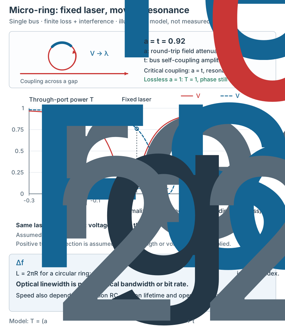
Figure 3 | Illustrative single-bus model: round-trip field retention a = self-coupling t = 0.92; dimensionless local wavelength detuning x, with θ ≈ −π(x − xres). A fixed laser samples two shifted resonances. The assumed tuning direction and curves are not data from the cited device. FSR and optical Q are distinct from electrical bandwidth and bit rate. Click for full size.
Materials and implementations
Thin-film lithium niobate (TFLN). TFLN is a material platform, not an alternative to MZ: a TFLN IQ modulator contains nested MZMs. The 2020 paper compares conventional LN waveguide devices with active lengths 30–80 mm, Vπ around 3.5 V and bandwidth around 35 GHz; these comparison values are not universal product limits and should not be confused with a bulk Pockels cell. Its TFLN examples use Vπ = 1.9 V at 13 mm and 3.1 V at 7.5 mm, giving approximately 2.3–2.5 V·cm from those rounded values. The paper reports bandwidth/Vπ of 25 GHz/V, ER above 25 dB, and 320 Gbit/s at 80 Gbaud 16QAM, with BER 8.4 × 10⁻³ below its stated soft-decision FEC threshold[9]. This is an IQ/coherent result, not a 320 Gb/s binary intensity lane. A 2022 dual-polarization IQ study reports 1.6 Tb/s net single-carrier transmission and 12 dB insertion loss including PM-fiber coupling[10].
Graphene. A 2026 graphene–silicon slot-waveguide ring study embeds two graphene layers in the slot. It operates in a graphene transparency region and uses electro-refraction to shift the ring resonance, rather than using broadband absorption as its main modulation mechanism. At 1550 nm it reports Vπ·L = 220 V·µm, bandwidth above 70 GHz, 10 µm active length and a 50 Gbit/s open eye at 2 Vpp. The same device also shows a 20 Gbit/s open eye at 2 µm with 2 Vpp; the reported bandwidth above 20 GHz is limited by the measurement setup. Operation in two bands does not make an individual ring resonance broadband[11].
Plasmonics. Surface plasmon polaritons (SPPs) at metal interfaces confine optical fields and can support very short active sections. Field confinement, drive efficiency, electrical bandwidth and metal absorption must be evaluated together; short length alone does not establish low total link energy[3][9].
Electro-absorption (EAM). An EAM changes semiconductor absorption with voltage, rather than relying on a phase-to-intensity interferometer. It can be integrated with a laser as an EML[1]. Here it is a mechanism contrast, not another material category alongside TFLN and graphene. Its usable rate depends on the specific design and link conditions.
Integration is a separate comparison axis. The silicon-ring paper discusses CMOS compatibility and CPO integration as motivations[2]. Its research results do not establish a general commercial ranking of silicon, TFLN and InP. Packaging, laser coupling, yield, reliability and product-level qualification must also be checked.
Selection: compare test conditions
| Platform / structure | Mechanism | Reported result and conditions | Comparison limit |
|---|---|---|---|
| TFLN IQ (nested MZMs) | Pockels + interference | 320 Gbit/s; 80 Gbaud 16QAM; BER 8.4 × 10⁻³, with FEC[9] | Coherent IQ result; not a binary intensity lane |
| Si micro-ring: high-speed | Carrier control + resonance | 400 Gb/s PAM6; 2 Vpp; open eye[2] | Eye opening alone is not error-free delivery |
| Si micro-ring: self-biasing | Carrier control + resonance | 32 Gb/s NRZ; 0.43 Vpp, zero bias; 2 km, reported error-free[2] | 0.97 fJ/bit: calculated modulator-only energy |
| Graphene–Si micro-ring | Electro-refraction + resonance | 50 Gbit/s at 1550 nm; 2 Vpp; open eye[11] | Research demonstration; qualify loss and reliability |
| Plasmonic | SPP confinement + active material | No comparable rate/energy result selected here | Metal absorption and integration trade-offs[9] |
Select in this order: first decide which field quantity the receiver needs (intensity or coherent IQ); then choose a suitable readout architecture and material; finally compare bandwidth, drive swing, loss and thermal control under the same conditions. MZ reads a differential phase; a ring samples a voltage-shifted resonance. Both can use several material mechanisms, so neither architecture implies a single material or an automatic low-energy advantage.
The table is a record of research demonstrations, not a performance league table. Compare wavelength, format, baud rate versus bit rate, raw versus net rate, eye opening versus BER/FEC criteria, and the system boundary used for energy. The cited sources still do not provide an equal-condition cross-platform comparison or complete long-term reliability, cost and yield data. Book references [4]–[6] retain the original links; precise edition/page access should be added when available.